
Nearly two years ago I bought four G1-7B tubes to make another linear amp. Progress was good and I estimate I was a couple of weeks away from full on testing. Timer board and power supplies were all tested. The tuned input and the tank circuits were all good as checked with the AA30 analyser. All that is left to do is one grid meter and its wiring, a keying jack, a 5 volt supply for the input band relays, two indicator lamps and re-activation of a couple of the four tubes.
Progress came to an abrupt halt when my lovely wife, 50 years married, died. I had never known or imagined such grief and abject misery.
I have now finished this linear and put it on the air on 21 November 2015.
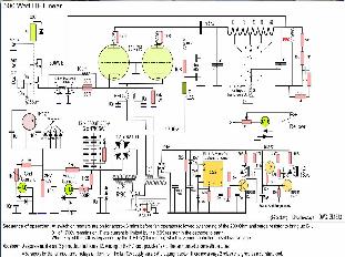
Here are some comments and pictures. Much of the idea comes from Fritz at pa0fri, a mine of info. There are many GI-7B ccts about. My own power supply and timers etc may be different and the layout of course is always a head scratch but the fundamental RF circuits are all similar. My effort is no different, and it works.
Re-activation.
These tubes run HOT and my first attempt to re-activate just one on the bench melted the tube.
The pin at the bottom nearly fell out. The heater volts were just marginally high at 13.2v and I had no fan on it. It seems these tubes like a blower even with only the heaters on. I suppose you all knew that. (I replaced the melted one)
Click the pics to enlarge
(Pictures tell a thousand words)
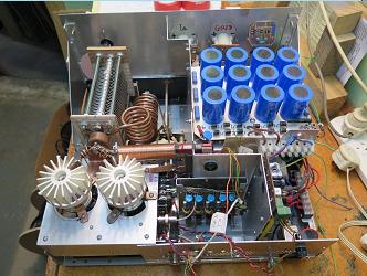
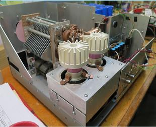
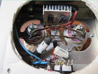
A pair of Gi-7B tubes are wired underneath similar to Fritz, PA0FRI.
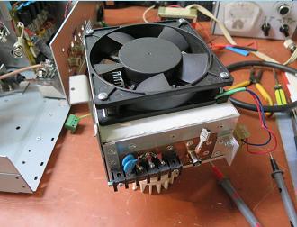
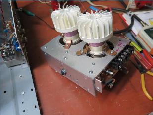
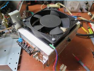
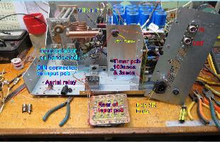
A 12v fan is mounted underneath blowing upwards and cylinders surround tube anodes to contain airflow. The cylinders are from rainwater down pipe and split for easy removal/fitting. The fan is mounted against a 1/8" thick soft material to reduce noise and any vibration. Bent copper clips clamp the tube's grid flange firmly onto the ground plain. The whole RF module can be removed quite easily. An 800va toroid is on chassis base under the rectifier/filter C pcb. The AC from the toroid is connected to the rectifier board via a terminal strip. It is useful to lift this AC input when testing later and when only the low voltages are needed. Although care is still needed (230V) it is relatively safe with only 28vDC and the htr 12.6v ac live.
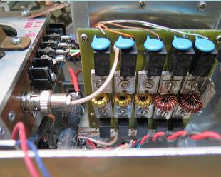
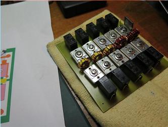
Pairs of relays are selected with a wafer added on the band switch shaft. Ceramic trimmers adjust for min SWR. A solid state rig with auto tuning will drive it without going mad. The tuned input is based on WD7S TU-6B board but I can't recall where the component values came from. The tuning for min SWR was done with an AA30 analyser. A 1/4w resistor was used as a dummy load on the pcb output and each pair of relays energised in turn. The dummy load value used was 50R+ the 25R which is in series, total about 80R for 10/15/20/ and 40 mtrs. At 80mtrs the impedance is lower and I used just 50R. Even that is high.
See Dominique's site F1FRV and scroll down triode amp linear boards page.
My input board relays were 5V, no 12v version left. A series dropping R is used from the 12V fan supply since the relays are always a constant load.
My anode choke has ferrite rod inside which renders any resonance well away from our op' frequencies.
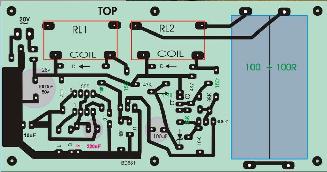
PCB mounted vertically has timers and relays for switching on sequence. Tube heaters are given nearly 3 mins before B+ is available after an anti surge delay of 3 secs. The fan also comes on after the 3 mins.
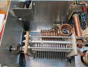
I now use ceramic tiles for capacitor end plates.
Arcing is less likely with ceramic, 'honest!
The material is ideal and manageable with care. My minimum capacitance at about 25pF seems a bit too high for 10mtrs, be aware.
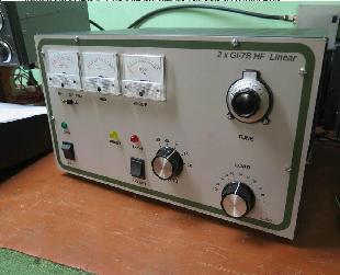
On left is finished amp. Linearity is copybook perfect on all bands and power output up to 600w pep is ok.
My meters are 50uA units with shunts and multipliers to suit for B+/rel pwr, grid current and anode current.
A seperate 12v winding supplies the fan and 5v input relays via another rectifier.
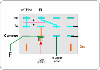
The aerial relay is modified to perform as shown and works well. Courtesy Lloyd - ZL1LA.
Bottom center pic shows preselect switch for bias zener voltage. Z=15,16,18,20v. Depends largely on B+ voltage.
