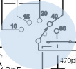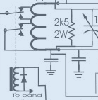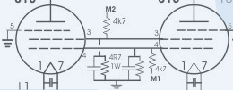


At time of writing the tank coil consists of three separate coils joined in phase. The low frequency part is 18 turns of 3/16 copper tube dia 3" and length 5". The 20 and 15 mtr taps attach to a 1/4" copper tube coil 5 & 1/2 turns at 2" dia. The 10 mtr part is abt 3 and 1/2 turns of 5/16 copper strap and dia 1.5". The picture offers the idea.
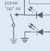
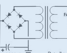
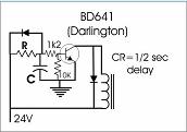
RL2 is actually a second separate relay to switch bias voltage and is supplied via a relay delay. That relay coil and delay cct are not shown on the above cct. It seemed a good idea to allow the antenna relay to settle before any power applied. The relays are off the same "op" panel switch or P to T arrangement. Bending relay contacts and messing with armatures was not my preference. The transformer I used for relay supply is an 18V AC output rated at 2.2 amps. It is one I happened to have and on load it delivers nearly 23 volts dc after bridge rectification. Not a problem since relays switch at about 15 volts.
RL2 is actually a second separate relay to switch bias voltage and is supplied via a relay delay. That relay coil and delay cct are not shown on the above cct. It seemed a good idea to allow the antenna relay to settle before any power applied. The relays are off the same "op" panel switch or P to T arrangement. Bending relay contacts and messing with armatures was not my preference. The transformer I used for relay supply is an 18V AC output rated at 2.2 amps. It is one I happened to have and on load it delivers nearly 23 volts dc after bridge rectification. Not a problem since relays switch at about 15 volts.
The same delay circuit is used in the power supply for soft start. It is useful to use a pot for R, say 10K or more depending on the C you have around.
Click on the colour shading for a picture in a new window.
A note or two about some favourite tools.
Most tool needs are obvious. Anyone contemplating this sort of construction involving metal chassis work, boxes, brackets etc might find the rivnut tool a real bonus. A rivnut tool is one item I would not do without. One rivnut tool will rivet several different sizes of nut onto an ali panel and it can save hours.
Another recommend is the Almost All Digitial Electronics C and L meter. See AADE web site.
It is quite accurate and quick and easy to use and light on batteries.
Then there is the artwork needed for front panels. Almost any graphics programme can allow drawing a panel layout. Word processors can do it too. Just measure up the panel - I usually scan it then draw over it and remove the scan picture when done. A full size print, with all the fancy detail and colour you want, can be made and then laminated. A roll of wide double sided tape (3M??) can then cover the back of the lamination and with perfect alignment, is placed on the front panel. Perfect alignment is essential. Start at one edge with only a thin strip of backing removed then pull away the backing progressively ensuring no air is trapped to cause bubbles. There's a nack to it.... After it's in place the holes can be cut out.
Several versions of tank coils were tried in an effort to lift output on 15 and10 meter bands. Taps were set up by feeding 5 or 6 watts back into the output with a simulated plate impedance of around 2K5 to 5K across the tubes. Only the antenna relay is energised, strictly no B+. It is safe to tinker. Taps and tuning is chosen for lowest SWR on each band starting at 10mtrs. That simulated load needs to be non/low inductance.

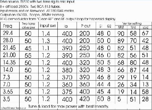
Here are the numbers for the latest version. The screen grid current is small, it has been seeen to go slightly +ve. These figures were achieved by adjusting for maximum output with excellent linearity. All frequency bands could be driven harder but high plate current and distortion can result. It is my understanding that the power shown on the meter derived from a two tone input is doubled to give the SSB output. Finally, I have to say, tuning this linear for clean output without a scope and a means of sampling would be about impossible. Perhaps it is no wonder some sigs on the band are not so good to listen to. SSB monitor scopes were clearly not on the market for no good reason 30 - 40? years ago.
Click on pics to enlarge.

Meter switch
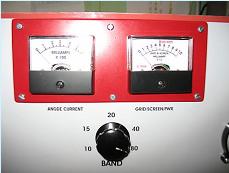
Lloyd ZL1LA points out, amongst other things, that the second pole on the grid meter switch is redundant. Well - one pole is fine if everything reads negative and we put the rel' power diode right way round as well. However - I never knew whether screen grid current ran pos or neg and noted it can go a bit either way. The last test run showed it to be from 0 to 8 mA(-ve). So - I have removed the second pole on the circuit. The meter for both grids and the rel power indicator read negative current.
Lloyd ZL1LA points out, amongst other things, that the second pole on the grid meter switch is redundant. Well - one pole is fine if everything reads negative and we put the rel' power diode right way round as well. However - I never knew whether screen grid current ran pos or neg and noted it can go a bit either way. The last test run showed it to be from 0 to 8 mA(-ve). So - I have removed the second pole on the circuit. The meter for both grids and the rel power indicator read negative current.
NOTE the loading capacitor on 40 mtrs was fully meshed when only the variable 1340pF load capacitor was fitted. The addition of a fixed 470pF has fixed that.

Next step is an enclosure for the linear and a lid for the power supply.
Protracted testing calls for a little air around the dummy load. Even warm air is better than none. Another point - especially if using a boat anchor for tests, check the input two tone wave form often and especially when changing bands. In other words - like when in QSO, watch the mic gain. Too much and it makes a hideous mess of linearity.
Linearity note:
In all of these tests it is noted with interest that tuning for maximum power on the meter is not any proper indication of good linearity. It becomes quite clear that sacrificing just a few watts of power can almost always render linearity perfect instead of imperfect. All we need do generally is unmesh that load C just a tiny bit to clean things up.
In all of these tests it is noted with interest that tuning for maximum power on the meter is not any proper indication of good linearity. It becomes quite clear that sacrificing just a few watts of power can almost always render linearity perfect instead of imperfect. All we need do generally is unmesh that load C just a tiny bit to clean things up.
Problem 1.
After a week of bench testing with two tone input and dummy load a QSO seemed in order. I loaded up to about 400 watts with perfect linearity and was happily talking to EA7BA and "bang". The fuse vapourised and my lovely trapezoid turned to fuzz.
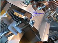
Here is what appears to be the culprit. Arcing across the tufnol insulator on the tuning capacitor.

It developed into quite a firework display under test so was easily spotted with the cover off. That brass tag with the hole is where the 10KV blocking capacitor is screwed on and very much the "business end" of things. Heh - thank heaven for rivnuts, I don't even have to get underneath. Anyway - we will replace the offending part and try a bigger gap if possible.
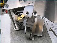
All done, tufnol removed and bigger gap made.
All done, tufnol removed and bigger gap made.
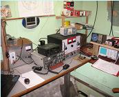
And here was I thinking I had finished building my 813 linear. All set up for a qso and a bit of DX.
I really must replace my 40 year old map of the world.
I really must replace my 40 year old map of the world.
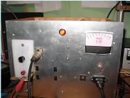
Got a good 500uA meter and with a bit of advice from Lloyd, ZL1LA, put it in series with the bleeder R nearest the earth end and a 200 ohm multi turn pot as a shunt to read FS at 4KV. Pic shows my 2900 volts off load. Mains voltage was a healthy 230 volts.

