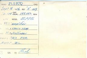

Towards the end of 1976.
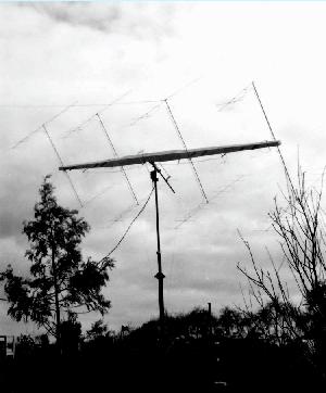
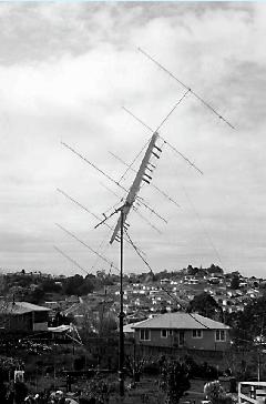
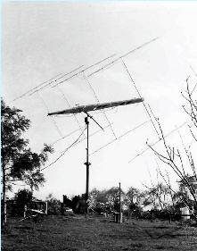
The yagi antenna pictured here was a successful EME array on 144 Mhz.
The boom was a tapered wooden box spar skinned with marine ply and 36 ft long. The eight yagis were 10 elements each and arranged four over four as seen. It was fitted on a polar mount to track the moon.
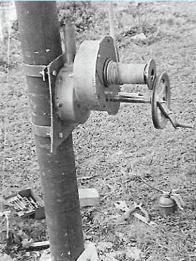
A winch made from an old hoe gearbox raised/lowered the beast. The array gain was deemed to exceed the minimum 20dB needed for EME.
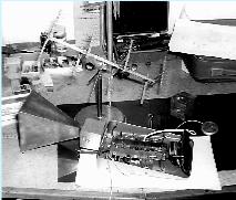
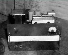
A tin and copper wire model of the array was built for fun rather than any practical purpose! In the foreground is a Gunn Diode transmitter and modulator. Yes, I managed voice comms across the whole of my garage with it!! The horn is of copper sheet, the cavity milled out of a solid ali' block.
Frequency somewhere around 10 Ghz! Power supply about 7.5 volts, modulated.
Frequency somewhere around 10 Ghz! Power supply about 7.5 volts, modulated.
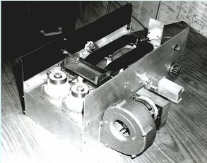
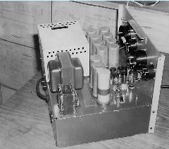
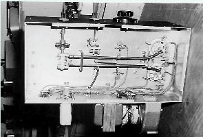
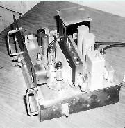
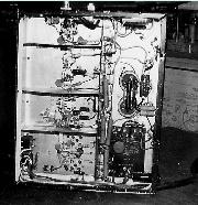
This lot was driven by a homebrew pair of 4CX250s in push-pull. They were fed from my homebrew transverter which was in turn driven by my FT DX400. I recall somehow we derived 10 watts from it to drive the transverter.
Much of the work for this challenge was done by ZL1LA. He built the power supply, control ccts etc and most of the aerial array harness using 300ohm cable. His input was most valuable.
There was plenty of building going on around this time!.
Much of the work for this challenge was done by ZL1LA. He built the power supply, control ccts etc and most of the aerial array harness using 300ohm cable. His input was most valuable.
There was plenty of building going on around this time!.
The aiming for EME contact was eventually calculated using a basic programme imported from Europe. It took me several days to get it to run the Southern hemisphere numbers. The computer used was a NZ$500 homebuilt kit, a UK101. It ran an 8kb Ohio Basic in ROM.and I think it had 8kb memory. The speed in "turbo" was 2Mhz.. It took all morning to calculate and print a few hours of az-el data on a dot matrix printer! But it did the job. A borrowed aircraft swinging compass also helped. We also played ping-pong on the UK101.
The Moon is not always visible of course. Using az-el data we could aim ahead of sked times. We really only had a couple of mins or so without re-aiming. We needed motor driven tracking but never got that going.
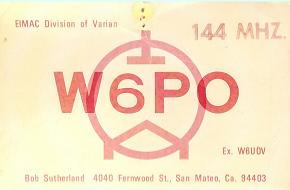
This array featured in the Moonbounce Group 2 publication by W6PO, Bob Sutherland, Eimac. It included some of these pictures.
On the left is the winch made from remains of a rotary hoe. A good hoe was made from two - these are left over bits..
EME - HISTORICAL INTEREST !
4CX250s
2 mtr transverter
Power supply. A second identical transformer was paralleled with this one to maintain voltage under full load.
EME Antenna
Most of the gear for EME in 1976 at ZL1BJQ.
Lloyd, ZL1LA built the power supply and much of the linear. It was very much a shared project
Lloyd, ZL1LA built the power supply and much of the linear. It was very much a shared project
Click for a bigger view
