The inspiration for this linear and 95% of the information needed to build it has come from F.H.V. Geerligs. His web site is a truly great source of help for many home builders. See http://www.pa0fri.geerligs.com/
for as good a start as you'll ever need.
for as good a start as you'll ever need.
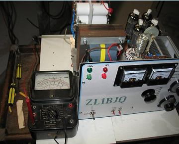
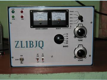
Probably the best part of my linear, the front panel. I have used Coreldraw for so many years now I can't remember. Simply draw up the picture, have it laminated, and stick it on. The laminate is tough material, it does a good job and you can draw all the detail and colour you need.
Click the pics
for a bigger view
for a bigger view
I was encouraged to choose this particular linear largely because so much info was available, and also because of an offer of ten PL519 tubes, all ok and including four brand new. They are also quite rugged according to all reports.
To help on the way I built a two tone oscillator, a keyer, and I accessed the old TS520 bias to adjust power output to drive it not wanting to risk my 'delicate' new FT450.
My 40 year old Sanwa multimeter had a 5000Volt DC socket/scale on it, brilliant. Better than today it seems.
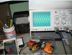
A new 30 Mhz Hameg 'scope more or less completed test gear needed but for a dummy load. Well, with tongue in cheek I built one of those jars of water with a little salt in it. I added salt until results, at 100Watts, exactly equalled results using my 100 watt Vishay non-inductive resistors. Seems to work ok and 400 watts won't bother it.!
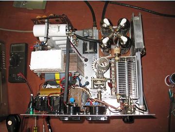
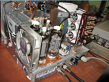
I do not have a complete circuit on paper in one place. Whilst that may be frowned on the circuit options are chosen mostly from Frits's web site. I elected to use a 40Volt heater transformer because I had one and prefered that to a series 230V heater chain. The individual tube bias controls were chosen in the event that tubes with different characterisitics were mixed and easy control is availed.. The power darlingtons needed were cheap enough and available. A solid state relay is switched by comparator sampling the B+ voltage, in my case 1440V off load. The relay bypasses a resistor in series with the mains input to the tfmr when the B+ sample of 5 volts drops. The circuit also offers a useful soft start function at switch on. I have also used a varistor. A suitably rated SSR was found fairly priced at Surplustronics. The circuit idea for that is found in the VHF Communications 4/88 by DL8MX/BB1NV. It calls for a heat sink, both the dropping R and the relay are mounted on it.
The polystyrene block and the wooden block are simply to allow standing on that side.
The polystyrene block and the wooden block are simply to allow standing on that side.
Picture on the left shows trusty old Sanwa meter reading the 1440 Volts.
The tank circuit was not right. I had to resort to feeding a few watts back into the antenna socket via an SWR meter and with a 2K resistor across the anodes to earth. An outboard 10 volts DC activated the 12 Volt antenna relay whilst the tank coil taps were found for each band. The RF power for this test came from a TS520 with the bias control in operation via the rear socket. The 2K resistor "load" was an old metal film type....made of two 1K in series and.rated at 2 Watts. I did the tests with about 5 watts, short bursts at a time and got away with it ok. This safe procedure was remarkably successful and quite easy to do. Don't hesitate - do it!
After that, I was able to dip and load in the normal manner. So far, after seeing a clean pattern on the 'scope, I enjoyed a rag chew for nearly two hours on 40Mtrs with my friend Peter, ZL3AQN. I used 60 watts from my FT450 to drive the linear and it seemed to perform quite well. One report said it was worth 2 S points.
More work is needed on linear testing, but the fine wx called me outside to finish a hexbeam.
Thanks to Brian, ZL2HN for a decent choke, and Lloyd ZL1LA for the tubes, and of course for all that info and circuit data on Frits's web site.
Here's a few miscellaneous pics. (Click to enlarge)
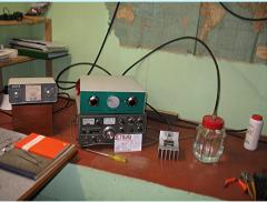
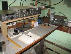
Operating position.
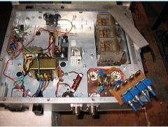
Early days under the linear.
Dummy load play. The jar of water was "salted" to give same results as the 100Watt non inductive load seen on the heat sink. The phosphor bronze strips as electrodes in the jar always spring outwards to the same position.
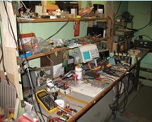
A bit of workspace.
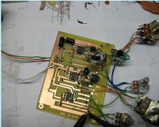
Two tone test oscillator pcb.
Couple of Wien bridge osc's and a mixer.
Couple of Wien bridge osc's and a mixer.
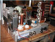
Linear under construction.
Now has a bigger fan.
BIG mains tfmr!! for next linear.
Now has a bigger fan.
BIG mains tfmr!! for next linear.


July 30th 2010, this linear has been in operation on 80, 40, and 20 mtrs now for well over two months and appears to work very well indeed with excellent reports from both local and dx stations. I constantly monitor the output on the 'scope.
Here is a transformer for my next 813 linear now started.
Here is a transformer for my next 813 linear now started.


