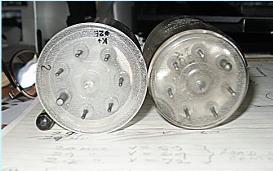
Lovely New QQE06/40 tubes.
WhenI tried to fit the new tubes into my sockets they would not go through the hole in the copper ground plane. The new Philips tubes had the 2mm extra glass rim round the base. Enlarging the holes having wired everything up underneath seemed daunting with visions of starting again. However various rotary abrasives got the job done quite easily. I think only Philips made the tubes with the wider glass rim.
WhenI tried to fit the new tubes into my sockets they would not go through the hole in the copper ground plane. The new Philips tubes had the 2mm extra glass rim round the base. Enlarging the holes having wired everything up underneath seemed daunting with visions of starting again. However various rotary abrasives got the job done quite easily. I think only Philips made the tubes with the wider glass rim.
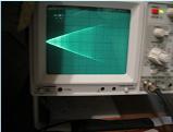
This shows one linearity test of many and typical of the results on all three bands on SSB at 400 watts peak power.
More about the above linearity test at CleanRF, or of course the various handbooks.
If you use or copy this circuit or parts of it then ALL responsibility for any outcome is yours, not mine. Voltages here are lethal, be warned.
About the relay.
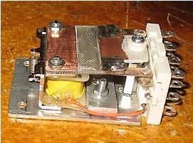
The RL2 relay switching the 1100 volts is a rebuilt modified 24v dc 4 pole 2 way relay.
The picture shows the end result. The end result provides a single pole two way unit with two wide spaced contacts in series to connect 1100 volts B+ after the 30 second delay. It seems to work well and was initiated by suggestions from ZL1LA.
The contacts are also straddled with a series R and a 10n capacitor to minimize arcing.
Some of the help for this linear, my third one, has been acknowledged. In particular F.H.V. Geerligs web site could be much to do with it all. Lloyd ZL1LA also has been very helpful in several ways. All will agree that talking about these things is one thing but actually building it is just a bit harder sometimes. But at the end of the day when it works it is a great satisfaction.


My first attempt is shown above and outlined here. Many hours were spent trying to get enough screen power from the rectified RF input. In the end it was decided to add another supply for screen volts and include the negative bias and relay volts along with timers and interlocks. Much help from Lloyd, ZL1LA encouraged a complete rebuild.
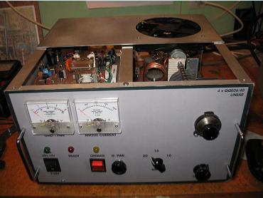
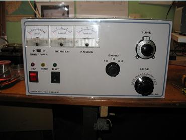
The rebuild with added power supplies is shown above and has reached expectations, namely at least 450 watts on 10/15/and 20 mtr bands with good linearity. Note metering for screen current. To establish viability a bread-boarded supply for the required voltages was jumpered across. Results looked promising enough to proceed.
Nearly all the major parts were re-used although some were modified. The tank coils were re-sized and tuning cap was re-made. The new box was a bit bigger....etc.
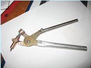
Boxes can be bought, at a price. It seems more appropriate to make one. I bought a useful fistful of varied aluminium sheet cut-offs, some rt angle lengths and some U section too. A word about tools too. 1/8th rivets and a pop riveter, a jig saw, and drills are obvious needs. My rivnut tool was put to good use again and ALL the panels are easily removable held with 4mm screws into rivnuts. The whole box assembly can be held together with Clecos whilst working out the next part and then further drilling. Modern Clecos are easy to use with the right tool and hold panels firmly in place as a temporary re-usable rivet. (Used extensively in the aircraft industry for years.) Take my advice, buy the pliers if you tread this path.
Boxes can be bought, at a price. It seems more appropriate to make one. I bought a useful fistful of varied aluminium sheet cut-offs, some rt angle lengths and some U section too. A word about tools too. 1/8th rivets and a pop riveter, a jig saw, and drills are obvious needs. My rivnut tool was put to good use again and ALL the panels are easily removable held with 4mm screws into rivnuts. The whole box assembly can be held together with Clecos whilst working out the next part and then further drilling. Modern Clecos are easy to use with the right tool and hold panels firmly in place as a temporary re-usable rivet. (Used extensively in the aircraft industry for years.) Take my advice, buy the pliers if you tread this path.
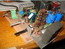
Left and right pics show early versions of the bread-boarded screen supply which needs good regulation. A minimum 280 volts was the aiming point and reverse current has to be catered for. A second tranny here provided for negative grid volts which was variable via a pot to a max of -40v. Only a few mA grid current is allowable, none is even better. A new toroid eventually replaced these tfmrs.
The above pic also shows the "finished" front panel cut in half. This was to make tank circuit changes, add flex couplers, reposition the band switch although the whole assembly could be removed . The new box would allow more space for those needed couplers.
Click on the pics for bigger version.
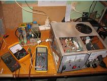
Talking about metalworking tools brings me to electronic tools. How we built anything fifty years ago without these digital electronic miracles I can only guess. One such instrument is the AADE meter for measuring L and C quickly and accurately. We now also have very clever antenna analysers and this instrument is doubly useful when building linear amplifiers. Tank circuit and input circuit tuning and matching becomes a relative breeze. For tank cct measurements antenna relay volts are needed.
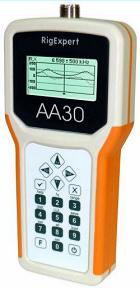
A very low wattage low/zero inductance load to simulate tube(s) impedance is also needed. And, for HF work, an AA30 Rig-Expert analyser. It is now a faster and safer process.
There are many other makes, I only know this make is brilliant. Only comment, get an AA54. Check them out.
A very low wattage low/zero inductance load to simulate tube(s) impedance is also needed. And, for HF work, an AA30 Rig-Expert analyser. It is now a faster and safer process.
There are many other makes, I only know this make is brilliant. Only comment, get an AA54. Check them out.
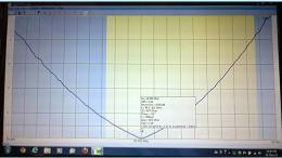
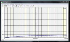
Above left shows a photo of my laptop whilst tuning/loading the tank cct at 28.4 Mhz into 50 ohms using my AA30 and supplied software. The right hand chart is the format that can be saved/copied as a picture file and shows a "full range" (0 to 30 mHz) plot of my input SWR after tuning the small L C input components. The instrument can be selected "continuous" so results of adjustment can be viewed almost as they are made. A scan takes a few seconds. These analysers may be used with or without the computer.
As well as "Antenna Analyser" it has a number of other uses.
As well as "Antenna Analyser" it has a number of other uses.
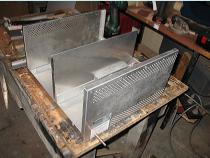
Above is the start of my box using panels from commercial equipment discards. Good if you can get them.
Just a few 1/8th inch Clecos can hold the lot together to maintain registration for more parts/holes before final reveting. One only is shown here.
Just a few 1/8th inch Clecos can hold the lot together to maintain registration for more parts/holes before final reveting. One only is shown here.
Recalled from the earlier attempt but still valid info.
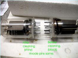
The pins on these old tubes seem to go black and need cleaning before use. Well, I cleaned mine as I had an unsure indication it might be a problem.
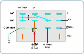
The pic on the left shows the TX/RX relay, another 4 pole two way unit arranged as shown. In receive the linear amp is bypassed and the linear screens are earthed, 280v screen supply is removed. On tx the linear is fed from transceiver and linear output to the aerial. Screen supplies are connected.
Looks like I need another page for the circuit, a few more pics, and some test results.

