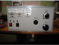


The major part of this re-build, the reason for it, was the need for a screen power supply. This brings with it the need for additional timers and interlocks. The tubes will be destroyed if this high screen voltage is applied without anode voltage. The new power supply addition uses a custom made toroid
Power rating: 51VA. Primary: 0-230V @ 50Hz.
Secondaries: 0-230V @ 150mA rms + 0-24V @ 500mA rms + 0-40V @ 100mA rms
Power rating: 51VA. Primary: 0-230V @ 50Hz.
Secondaries: 0-230V @ 150mA rms + 0-24V @ 500mA rms + 0-40V @ 100mA rms
The 230 volts winding is for the regulated screen voltage, the 24 volt winding is for timers and relays, the 40 volts for negative bias.
Toroid was made by Canterbury Windings.
http://www.canterburywindings.co.uk/
Toroid was made by Canterbury Windings.
http://www.canterburywindings.co.uk/
New amplifier
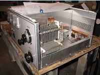
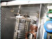
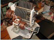
Tank circuit and empty tube space.
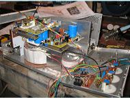
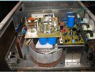
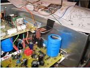
Left shows position of parts, the smaller toroid is hidden under the right side associated pcb.
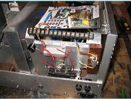
The 800VA toroid provides B+ and heater volts. Heaters are 12.6 and floating. A dropper was required to trim the voltage to 12.6 and the piece of copper(waveguide) is the heatsink overkill!.
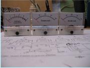
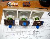
The relay seen in the middle is a 1 to 2 second delay and shorts out the 50 Ohm anti surge resistor needed for the toroid. The black terminal strip carries soldered connections from the toroid and spade terminals allow connections as required. The black fuseholder is for the B+ fuse. The lower pic shows meters and their 10 turn trimmer pots.
The B+ 35sec timer relay 2 on the top above the capacitor bank can be seen. The bleeder resistors and timer relay 3 are also there. Fuses on the rear panel are for mains inputs to the two toroids. If B+ is lost so is screen voltage.
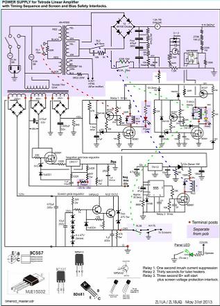
This circuit has evolved over a few months and after much prompting and regular interchange from Lloyd ZL1LA. Without his input, (and parts), I could well be still scratching my head. This is what I have built and finally tested and it works well. It could well serve other tetrode linears with appropriate minor adjustments.
At switch on timed RL1 holds open for 2 seconds before shorting the 50R which is in series with the 800VA toroid primary. Timed RL2, driven by a 555 timer, holds off the B+ voltage for 35 seconds to allow tube heaters to come to temperature. When RL2 closes then timed RL3 is started by a sample voltage taken from across a 10K part of the B+ bleeder chain.
After 2 seconds RL3 shorts out the B+ surge limiter. RL3 however can only operate if the negative grid bias is available to turn on the BC327 in series with the relay supply. The second set of contacts on RL3 carry the screen voltage so that if B+ fails the screen voltage is also cut off.
After 2 seconds RL3 shorts out the B+ surge limiter. RL3 however can only operate if the negative grid bias is available to turn on the BC327 in series with the relay supply. The second set of contacts on RL3 carry the screen voltage so that if B+ fails the screen voltage is also cut off.
The second set of contacts on RL3 is in series with contacts on the antenna relay and which is effective in allowing the tubes to turn on or off as required by keying the transmitter. These interlocks should prevent tube destruction should B+ or grid bias be lost. Removing screen voltage effectively cuts off tube current.
The RF circuit.
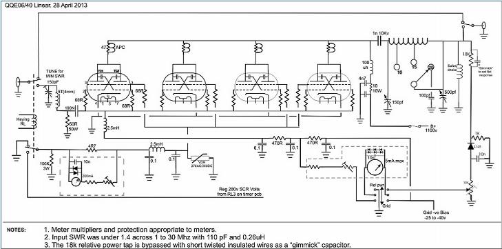
Derived mostly from http://www.pa0fri.com/ and VK3NX who used 3 tubes on 6 mtr band. It is not known if a 4 tube HF linear using QQE06/40 tubes has been made. I couldn't find one. I look forward to Lloyds(ZL1LA) version, whose idea it was anyway, but I had more time.
Derived mostly from http://www.pa0fri.com/ and VK3NX who used 3 tubes on 6 mtr band. It is not known if a 4 tube HF linear using QQE06/40 tubes has been made. I couldn't find one. I look forward to Lloyds(ZL1LA) version, whose idea it was anyway, but I had more time.

B+ is just over 1100 volts. Grid bias was initially set to -33 volts. Quiescent current for the four tubes is now set to about 135mA. I did have it at 170 and got told off by ZL1LA saying it was too high. The drive power needed is around 15 to 18 watts for typically 450 watts out and allowing under 1mA of grid current. As with most linear amps after tuning for max CW power linearity can invariably be improved by reducing the load C just a tiny bit. On air reports are accordingly very good indeed.
I am obliged to state categorically that this amp is the result of amateur radio activity and if copied in whole or in part I will accept no liability for results or errors. The risk is entirely yours and dangerous voltages are used..........................ZL1BJQ
Since this run the quiescent current has been reduced to about 135mA.
More power can be extracted and on 20mtrs I did manage to see 520 watts on the meter and linearity on SSB was quite good. Peak power almost made 600watts! It seems a bit pointless driving it that hard for so little benefit and more risk of problems.
More power can be extracted and on 20mtrs I did manage to see 520 watts on the meter and linearity on SSB was quite good. Peak power almost made 600watts! It seems a bit pointless driving it that hard for so little benefit and more risk of problems.
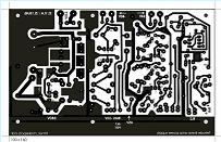
Finally if anyone wants to look at the pcb artwork for the two boards than please ask and I will try and send a file.
The relative power meter circuit has to be tinkered with to get a near flat response.
It is very useful for peaking up the power to max. But always back off that load C a tiny bit.
It is very useful for peaking up the power to max. But always back off that load C a tiny bit.
A few more pics on the way there.
All timers, screen, bias and relay supplies.
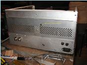
Rear. The perf strip is held with one screw into a rivnut. I might add a couple! Mains and screen fuses. Key jack
and in/out coax cons.
and in/out coax cons.
Ceramic tile is good choice for end plates.
I have had failures with plastic and tufnol.
I have had failures with plastic and tufnol.
Used 10 turn pots to trim multipliers.
Meters are 200uA FS cheapies from Ebay. (Most work fine, good value)
Meters are 200uA FS cheapies from Ebay. (Most work fine, good value)
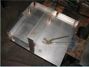
Tank circuit assembly is one sub-assembly held at the base by 4 rivnuts. One turn was bent down horizontal to reduce 10mtr coil.
Better pic of those temporary re-usable rivets, Clecos, great to use.
Re drawn dial markings. Remove face plate carefully. Any drawing program, turn plate over, use double sided tape.
Shows added heat sink on reg' screen supply. Weight taken on ali partition.


Additional protection is provided in the event of the B+ fuse failing. A SSR (LH1525AT) is energised from the B+ supply via series resistance to limit current to about 1mA. The SSR output in series with time relay RL3. A B+ fuse failure rapidly opens the screen supply.


