Enquiry with a local transformer manufacturer came up with a very high quotation. They clearly didn't want to make me one only 1100 volt 800mA tfmr! I recall it was about NZ$700. A bit like a red rag to a bull!!
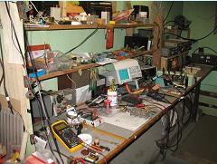
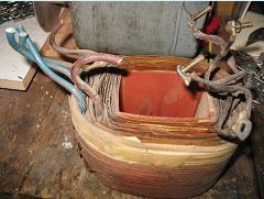
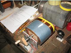
Top left pic shows an old tranny, one of two I had acquired too many years ago. It was labelled 65V 1KVA. Input 230V. It is too big really but too good to waste.
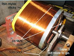
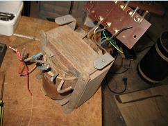
The next pic down shows the laminations removed. The blue and brown wires on the left were the 65V outputs (and taps), those on the right were 230V primary and a faraday screen which connects to the earthed frame.
The thick secondary turns on those blue/brown wires were removed, but the turns were carefully counted so I could work out the volts per turn. The volts per turn worked out to be 0.9. To make 1100 volts then required 1222 turns. I was fortunately availed a large reel of 0.4mm copper wire. We figured that since I would be looking for never more than 800mA and in CW or SSB service then it could be ok. We cut a meter length off and put one amp through it, there was no heat, it didn't even get warm. Is that a valid test? Well the chap that "lent" me the reel thought so and I had good reason to accept it. There seemed plenty of space on the bobbin too.
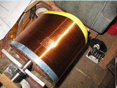
Leaving the 230V primary wires and screen alone, treating them carefully in fact, I placed a block of wood into the bobbin, a steel shaft through the center, and placed it across a couple of brackets screwed to the bench. On one end I put a handle - the other a turns counter. (not needed after all). The pictures tell all.
Between layers needs good insulation so I used a sheet of mylar and also a sheet of thick blue paper. This also made a good even surface to wind on. Progress was slow at first but practice allows quite an improvement. With luck, not judgement, 600 turns came up quite near the edge. I simply looped the wire out, about a foot, without cutting but twisted together, then carried on winding. That was hopefully to be a center tap. I used double sided tape in an under and over fashion to hold the windings near the edge. See pic on left. I also left a good 5 to 10mm space around the edges. More mylar/paper insulation goes across the ends during re-assembly.
On the last layer I made several taps to give me a good chance of finding the voltage required. The center tap was not really needed for this application but I thought is could be useful......
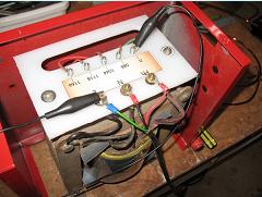
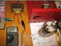
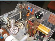
The pic 3rd down on the right is what I ended up with. Not too bad for a beginner, and even the center tap isn't too far off. The voltages are 0-588-1044-1118-1166. A doubler/rectifier cct will give me the nominal 3000 Volts DC (the B+)
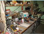
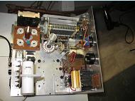
Bottom right is my heater tranny using same approach as above. A 60VA tranny with the secondary re-wound for an 813. And the center tap is about perfect too!
Don't forget to count those secondary turns before dismantling.....
Short Video clip here on YouTube.
Click on the pics for a bigger view.
This is in no way an instruction on how to make HV transformers.
It is simply how I made mine and this one is for an 813 linear.
IT IS A POTENTIALLY LETHAL PAST-TIME - BEWARE.
It is simply how I made mine and this one is for an 813 linear.
IT IS A POTENTIALLY LETHAL PAST-TIME - BEWARE.

or
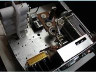
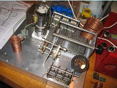
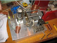
A few spare pics of the PL519 linear.
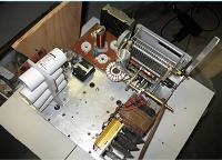
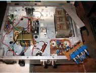
A collection of parts for an 813 linear. Will it all fit??
A work in progress......
Again - you are warned, this occupation requires great care.

