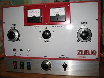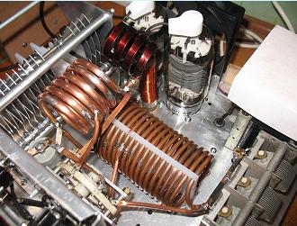

My first homebrew linear used used four PL519 tubes in parallel and works very well. That success encouraged me to try and make an 813 linear. It can be an addictive past-time!
The claimed performance and especially the 813 input circuit arrangement used by ZL1AXB seemed most attractive. The principle of this bifilar solution was also shown in SSB for Radio Amateurs. In consideration of modest power needs, the neighbours, the legal power limits and even the availability of tubes, a single tube version became the initial aim.
My junk heap had produced a 60V 1KVA 'tranny' which I could rewind for a perceived 2800 V supply. I must disclose at this stage that several people said that I should use two 813 tubes rather than one. I ignored them...for a while!
I seem to recall from too many years ago that a linear amplifier derived huge benefit from as high a B+ as possible and linearity was much dependent on a low impedance power supply. So I happily hung my hat on that idea and reinforced it with tales that 813 tubes were "rugged". I would wind my tranny with 3000 volts in mind but with a few taps. A voltage doubler circuit would be used, like everyone else uses. The voltage taps I ended up with would allow for some adjustment.
So beautiful.
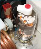
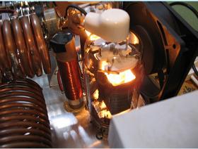
The 813 with its 10V 5A glow.
The 813 with its 10V 5A glow.
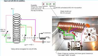
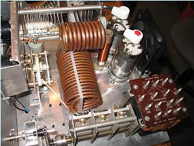
The original circuit did not cater for the 80 mtr band and so additional circuitry was needed. A much larger input coil and tank circuit had to be made. A relay operated by a microswitch on the bandswitch provides coil tap selction for 80 mtrs.
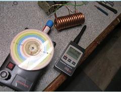
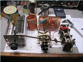
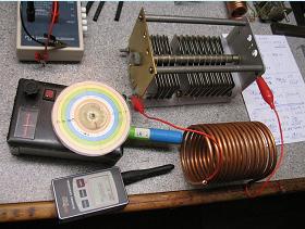
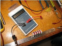
Early days establishing input coil tuning across desired range. One day I might finish the dipper but the F counter makes me lazy. It is also more accurate!
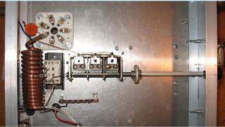
Keeping stray C and L out of things is hard to do. The twin (to reduce IR drop) white wires are teflon heater wires, the red wire thru the grommet is the heater tfmr center tap. The input SWR is a little high around 2 to 1 on the lower bands so changes will be made there.

IMPORTANT NOTE.
This 813 linear started as a single tube amp. A second 813 was added. Copy any of this at your own risk!! The cct is derived from a number of sources but with added innovation. As a single 813 linear it had allowed me to test acquired 813 tubes. The 2 x 813 version involved much re-building especially underneath but is now in regular use will good results. The 15 and 10 mtr band output is down more than we like, not unusual apparently, and needs attention. Linearity is copybook perfect.
Getting a feel for the tank coil. The tuning cap has been split with the time honoured effort to reduce minimum C for 10mtrs whilst finding enough for 80 mtrs. It appears I have too much minimum C, power just starts to creep up with tune and load caps out of mesh on 10 mtrs! That tank coil ended up with 18 turns of 3/16 tube at 3" dia and then 10 turns of 1/4" at 1"dia. I may need to rebuild or replace the tuning capacitor. The taps will need changing to allow for the lower combined plate impedance of two tubes. This programme can help no end with tank circuit design.

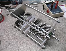
The tuning cap is 12 to 56pF and 19 to 140pF, a modified commercial unit.
Suitable tuning caps are expensive and/or hard to find. They are a lovely challenge to build and I may yet try one.
Suitable tuning caps are expensive and/or hard to find. They are a lovely challenge to build and I may yet try one.
I read so many specs for the safety choke it was hard to know who to believe. I do know that it needs to take out a one amp fuse with ease and requires a certain minimum L. I made 3 chokes before I got one down to 3.7mH and whilst it may still be higher than needed it seems ok. This choke must not be left out. Yes, there are easier ways......
Talking of chokes - the plate choke is a 3" winding of 18 guage copper wire on a 7/8" glass fibre former. The inductance is raised substantially with a ferrite rod suspended down it and hence any resonant F is reduced "out of sight".
DC volts drop is neglible.
Talking of chokes - the plate choke is a 3" winding of 18 guage copper wire on a 7/8" glass fibre former. The inductance is raised substantially with a ferrite rod suspended down it and hence any resonant F is reduced "out of sight".
DC volts drop is neglible.

Most of the pics on this page can be enlarged by mouse selection.
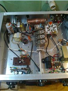
Not a prize winner but it is going to be rebuilt with two 813 tubes instead of the one. The PCB lower left quadrant is a delay cct for one of two change-over relays. Two relays are used, 'circuit shows one.
The antenna is then connected before power is applied, 'seemed a good idea. I didn't like the idea of bending relay contacts.
The tfmr RHS is to provide for the 24 volt relays.
The input tuning cap is mounted on hard plastic stand off insulators.
The relay directly in front of the coil is activated by the 80 mtr band switch selection and switches in the additional inductance and appropriate tapping point.
Top left hand corner near the aerial sockets has a tag strip mounted relative power take off to drive the panel meter.
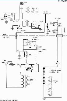
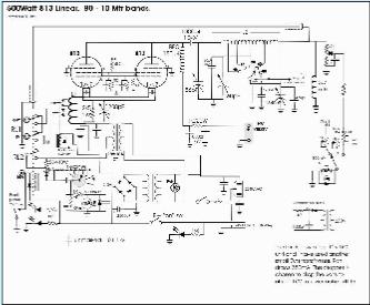
Some circuit notes
This circuit shows the additional 813 yet to be added. There are few other changes.
Quiescent current seemed low so the zener has been changed to 4.7V but with nine diodes on a rotary switch to offer considerable variation. We would hope to find two fairly similar tubes. A meter circuit has been added to show grid and screen currents and relative power output.
A seperate meter shows tube current. Meter ccts will be adjusted for two tube operation. When I first switched the linear on the screen current slammed the meter hard negative. A new good looking 4R7 resistor was open cct!! Ideally it seems a center reading meter would be better for G2. Screen current is just a few -ve mA. The cct shows G2 meter reads negative, like G1.
Some measurements whilst testing the single tube version are shown here and specifically on 20mtrs.
Input is from an old TS520. It still makes over 100Watts with original tubes and the meter is broken! Output is controlled with a 9 volt battery and a pot to feed a variable bias voltage into the socket provided on the TS520. Two tone input is fed into the mic socket. TS520 output is fed directlly though a demodulator(CleanRF) to drive the horizontal scope trace. Linear amp output is sampled with a simple RF coupling.
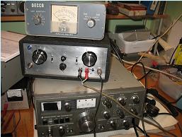
Input SWR and power is monitored on a Kenwood SWR meter. 813 linear output is fed to a 1.5 Kw dummy load via a Decca SWR/Power meter. It was calibrated against a Bird meter and also checks out ok with my FT450.

Above, the Decca meter, two tone oscillator, and TS520.
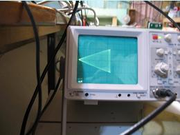
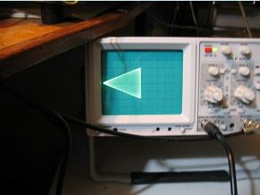
Below, 813 linear amp, two tones in, single tube output at just over 200 watts. Linearity is good, a bigger copy of the input.
Below, 813 linear amp, two tones in, single tube output at just over 200 watts. Linearity is good, a bigger copy of the input.
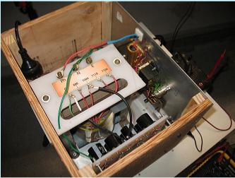
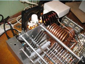
Top view, single tube. Another tube will be added and the heater tranny replaced...there is room.
I have some "new" 813 tubes on the way and this working single tube linear will make an adequate test bed for tube comparisons. After that the modifications will begin to add another tube and we will endeavour to wind up with a good quality linear with all the little bugs ironed out.
Just remember, this amplifier is not finished, there may be errors.
Finally - I have to say that tuning a linear for optimum output without risk really does need at least a demodulator, an RF sample, and a good oscilloscope, more especially if it is home brewed. How do you do it without??? I can recommend CleanRF advice. I have their demodulator, it is very good.

Power supply presently uses the lowest tranny tap and B+ on load at 200 watts dropped a couple of hundred volts to 2450. The higher voltage taps will be used later. 2800V may be manageable as a maximum.
PS: KEEP YOUR FINGERS OFF LIVE PARTS !!! I KNOW IT HURTS.

By the way
if you see overlapping lines on web pages try holding CTRL key and rolling mouse wheel forward one notch!
if you see overlapping lines on web pages try holding CTRL key and rolling mouse wheel forward one notch!
Power Supply
This circuit is fairly typical of the approach used by most builders needing high voltage for linear amps.
Great care is needed in wiring, earthing, insulation and choice of some parts.
The voltage produced by this low impedance supply is well past being LETHAL.
This circuit is fairly typical of the approach used by most builders needing high voltage for linear amps.
Great care is needed in wiring, earthing, insulation and choice of some parts.
The voltage produced by this low impedance supply is well past being LETHAL.
The only possible interesting bit is maybe the delay circuit. A Darlington relay driver is used, because I had them, and the CR value is chosen for a couple of seconds delay. During that time the surge current is via the 100 ohm resistor. A red LED is on the front panel but not shown here and a voltmeter will also be let into the front panel. After my own brush with death I am a most diligent user of a shorting stick. It is a 150K 3W resistor, because I had one, mounted on a long plastic rod and a aligator earth clip. Its use has become a religion and it takes about 15 seconds to bring the volts down. Without it you need to wait several minutes....but you all know that eh.....

The dotted line on the circuit represents almost a meter length. The power supply may go under the bench.
The high voltage cable interconnect was made from a length of 30KV rated flexible wire which was used for the 4th anode on old TV sets. I fed it into a copper screen taken from a coax cable and then covered that with heatshrink. As well as that screen earth I ran another substantial earth wire alongside firmly bolted at either end. For the low 24 volt control cable I used 3 pin cannon connectors and with yet another earth. Multiple earths might not always be a good idea but in this case I feel happier with them.
The first two 813 tubes I tried promptly took out the 1A fuse. The standard glass variety are not good at this voltage by the way and the sand filled ones should be better. The tubes were faulty, my power supply was ok.
Again - I take no responsibility for any outcome resulting from your use of this information.
The tuning capacitor.
The minimum capacitance needed reducing to better tune the 10mtr band so I decided to make another tuning capacitor.
It would be another two section variable.
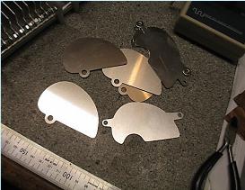
I drew up the plates and sent a DXF file to the laser cutters. They cut 26 rotor and 26 stator plates for me. There is no way was I going to attempt making those by hand. 'Tried it once some time back. (Anyway - I have enough left for yet another tuning capacitor).
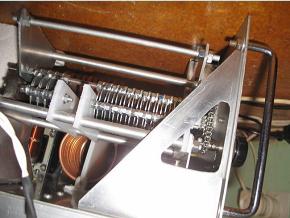
To assist with a low minimum C the shaft is offset. The stator of the smaller section is spaced away from the earthed frame with a block of tufnol. It can be seen in the pic. A good gap between rotor and stator is arranged when minimum C is set. This is mostly important on the small section of the capacitor.
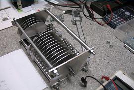
Final result seemed quite good at about 9pF to 57pF and the bigger section 16pF to 157pF. The 9pF minimum is nearly half that of the smaller section of the existing tuning cap so is a worthwhile step in the right direction.
The new variable is quite large at 100 x 110 x 180mm plus projecting bolts etc. Plate spacing is 3mm and plate thickness is 0.9mm. The spacing is generous but allows for possible lack of precision! It was a surprise to measure the variation in thickness between 6mm nuts even from the same batch. Next time I will measure every one and select equal thickness.
The spindle is 6mm threaded rod and the two stator supports are 4mm. (Originally 3mm but enlarged). These steel bits and pieces are zinc plated and so not a bad combination with aluminium in a dry environment. This new tuning cap will align with the existing front panel vernier and chassis space allotted.
Having used the single tube linear to test all the newly acquired 813 tubes I will dismantle it underneath, fit the newly made tuning variable, add a tube socket, replace the heater tranny and rewire it all as required for two tube operation.

The shape of the plates was derived from looking at a commercially made unit of similar size. No copy or measurements were made. I simply drew what looked ok and tried to make it to fit my existing space on the chassis.
The spacers are a crucial part of the assembly. It would be easier to use the same size of rod for the main shaft and the stator supports. That way the same size nuts can be selected to space both rotor and stator plates. A smaller capacitor may be ok with 4mm hardware, a bigger one 6mm. It would be debatable what size to choose but each and every spacer really needs to be a close tolerance part. It makes assembly far easier and an end result which can allow possible closer and consistent plate spacing. I don't find these easy to make, perhaps you will. I did drill out the threads in the nuts so they slide over the rods easily. The end nuts are used to clamp the lot together.
The spacers are a crucial part of the assembly. It would be easier to use the same size of rod for the main shaft and the stator supports. That way the same size nuts can be selected to space both rotor and stator plates. A smaller capacitor may be ok with 4mm hardware, a bigger one 6mm. It would be debatable what size to choose but each and every spacer really needs to be a close tolerance part. It makes assembly far easier and an end result which can allow possible closer and consistent plate spacing. I don't find these easy to make, perhaps you will. I did drill out the threads in the nuts so they slide over the rods easily. The end nuts are used to clamp the lot together.
The top side.....
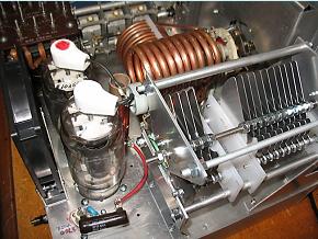
Another tube socket is fitted. A 12Vdc thin fan replaces the thick 230V unit. Space was tight!
The glitch resistor carrying B+ needs another support. That red wire is rated 40Kv, good stuff.
The new heater tranny needs a safety cover over all those terminals. It is too easy to drop a pair pliers.
All the tank coil taps have been removed. Combined tube impedance is said to be around 5k or 6k so taps will need to be re-established. I had to use another Kenwood ex TS520 chain drive to ideally position the new tuning capacitor. It is a good solution - and no backlash with the right tension on the chain.
Wiring underneath the chassis is the hard bit - it's a mess right now.
The ferrite rod can be seen suspended in the anode choke. The former is glass fibre.
REBUILD

Click on pics to enlarge.
On left is the chain drive and a hole cut for easier access. 'Works well.
Those little chain drives and plastic sprockets are great. They allow placing controls almost anywhere for whatever reason. The chains can be shortened by a link, maybe two, but removal of more links means the spring tensioner link has to travel over the sprocket and is not a good idea. Adding spare links is no problem. The spring tensioner needs to be just in tension. The chains/sprockets are from an old TS520.
Those little chain drives and plastic sprockets are great. They allow placing controls almost anywhere for whatever reason. The chains can be shortened by a link, maybe two, but removal of more links means the spring tensioner link has to travel over the sprocket and is not a good idea. Adding spare links is no problem. The spring tensioner needs to be just in tension. The chains/sprockets are from an old TS520.
Well I didn't call this link "813 saga" for nothing. It seems I need to rebuild some or all of the tank circuit. Why? Because like before the output on 15 mtrs is low and on 10 mtrs useless. I mounted a quickly made flat copper coil about 4 turns and soldered it into the 10 mtr position but out in the clear, with little coupling to anything. A test run showed the power out doubled to what is was. Now I had 125 watts showing on the meter, two tone in - so 250Watts PEP. You can see the solder marks where taps have been tried.
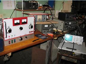
The pic on the left shows the testing effort. From left to right you may recognise the lumps. The linear, a KW103 pwr/swr meter for output sitting on top of a Kenwood AT SWR meter to monitor input. The two tone genny is sitting on top of the old boat anchor with the broken meter.
Yes - the TS520 still works a treat and allows not only the two tone input via the mic socket but adjustable pwr level using a nine volt battery and pot fed to the final tube bias.
The 35Mhz Hameg scope is fed with demodulated RF from a "Clean-RF" RF-D unit and a loop coupling from the coax switch on the way to the 1.5 Kw dummy load, out of sight.
On left is trapezoid pic whilst testing at 14.2 Mhz. Linear drive was 50 watts two tone from TS520. Input swr was 1.4 Output meter showed 290 watts and plate current was 350mA. (That equates to 580watts PEP). Whilst doing this test I dragged the Hexbeam ant' coax over and used the FT450 to drive the linear to get a 5/9 and a good report from John (EA7BA) in Spain on 14.156. I loaded up 400 watts, the same pwr as used with PL519 linear. My one and only qso with this rig so far.
There's that plate choke with the ferrite rod down the middle.
I don't think it's a problem.
I don't think it's a problem.

Tank circuit rebuild
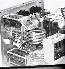
I started to look in books I forgot I had and found this pic (left) in SSB for the Radio Amateur. The layout in principle is now similar whereby coupling between coil sections is reduced. I re-checked the coil taps with 5 watts fed back into a simulated plate impedance of 3K3 and noted almost no difference from the 2K5 settings used before. Some books say 5K, some 2K5 and it hinges largely on the plate voltage chosen. On the right is what I tested. The improvement on 10mtrs and 15 mtrs is quite good. I may have to live with it because I am running out of ideas. Another 160 volts to B+ is available. At present, with 2650V off load, the last test for 28.2 Mhz showed.
pwr in(2tone)50W, swr in 2.1. Ia=400mA, pwr out on meter=200W. G1=50mA, G2=1mA.+ve
On 80mtrs I can drive the output to 410 watts on the meter with 55 watts input and that was just beginning to show linearity problems. Overdriven I guess and in practical use is not a sensible option. However, perfect linearity is achievable at around the legal power limit.
Yep, I'm running out of ideas, and solder!!
'Needs a bit of a clean up now.
'Needs a bit of a clean up now.
Hindsight
is a wonderful thing. Instead of trying to be clever and arrange my own old fashioned linear I perhaps should have built one of the well documented 813 linears others have perfected.
I recall now more fondly than ever the several Heathkits I built and when I never had these problems. Still, there is much satisfaction.


If and when I get a lid on it, a box round it, and go on air with it then I will update. To have read this far you must be mildly interested so if you have time there is one more page.


